


Injection Molding Design Guide: DFM Rules for Wall Thickness, Draft, Ribs, Bosses and Undercuts
A moldable plastic part begins with one resin-appropriate nominal wall, sufficient draft in the actual pull direction, ribs and bosses that do not create hidden thick masses, and a clear plan for every undercut. These rules reduce sink, warp, drag, flash, tool complexity, and late engineering changes. They are starting values for DFM鈥攏ot universal guarantees鈥攂ecause resin grade, flow length, surface texture, gate position, loading, tolerance, and annual volume can change the correct answer.
This injection molding design guide turns common DFM rules into decisions an engineer can apply before releasing CAD for tooling. The guide focuses on wall thickness, draft, ribs, bosses, and undercuts, then connects those features to parting lines, gates, ejection, tolerances, and the information a molding supplier needs to validate the design.
Quick DFM starting points
- Choose a nominal wall from the exact resin-grade data and keep it as uniform as practical.
- Use roughly 1鈥?掳 draft per side on ordinary untextured walls, then increase draft for depth and texture.
- Start rib and boss walls at 0.5鈥?.6 times the nominal wall thickness.
- Keep rib height near or below 3 times the nominal wall and add 0.5鈥?掳 draft per side.
- Core out bosses, separate them from cosmetic walls, and connect them with thin ribs or gussets.
- Redesign undercuts for a straight-pull tool when function allows; otherwise select and quote the mechanism before steel is cut.
What Does DFM Mean for an Injection-Molded Part?
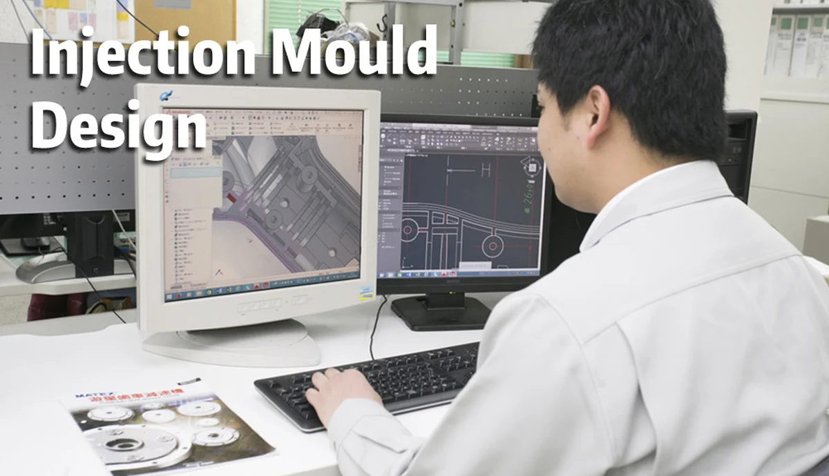
Design for manufacturability, or DFM, is the process of checking whether a part can be filled, packed, cooled, opened, and ejected repeatedly within its functional and cosmetic limits. A useful DFM review does more than highlight red CAD faces. It explains the defect or tooling consequence, identifies the variables behind the risk, and proposes a change that preserves product function.
The best time for injection molding DFM is after the product architecture and intended resin are reasonably stable but before the tool layout is frozen. A review performed without the resin grade, finish specification, annual volume, critical dimensions, and show surfaces can identify obvious geometry problems, but it cannot reliably approve the part for tooling.
DFM rules also interact. Increasing draft may change an assembly fit; thinning a rib may reduce stiffness; moving a gate may relocate a weld line; eliminating an undercut may alter a snap feature. The correct review therefore evaluates the complete part and tool concept rather than treating each guideline as an isolated pass/fail limit.
Which DFM Rules Should Be Treated as Fixed Limits?
Very few geometry ratios are fixed limits across all injection molding projects. A rib thickness of 0.6T may be acceptable behind a textured structural surface but too thick behind a high-gloss cosmetic face. A 1掳 wall may eject cleanly at a short draw but drag when the same texture extends over a deep core. A 1.2 mm wall may fill in a small high-flow polypropylene part but short-shot in a long glass-filled polycarbonate housing.
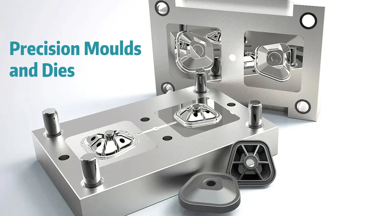
A sound DFM report labels each conclusion as one of three types: a geometric lock that prevents mold opening, a high-probability process or cosmetic risk, or a design preference that simplifies manufacturing. This distinction prevents teams from spending time on minor preferences while a true tooling conflict remains unresolved.
| DFM finding | Typical consequence | Required response |
|---|---|---|
| Reverse draft or trapped undercut | Part cannot release with the proposed tool action | Change geometry, pull direction, parting line, or tooling mechanism |
| Thick rib intersection behind show surface | Likely sink, read-through, or extended packing time | Reduce mass, relocate feature, or agree a cosmetic limit |
| Tight nonfunctional tolerance | Higher tooling, inspection, and scrap cost | Open tolerance or document the functional requirement |
How Should Wall Thickness Be Selected?
Wall thickness should be selected from the intended resin grade, flow length, load case, surface requirement, and molding process鈥攏ot from a generic material-family chart alone. Published ranges are useful for early CAD, but the final nominal wall should be checked against the grade datasheet and the supplier’s machine, gate, and flow analysis.
Most ordinary housings begin within roughly 1.5鈥?.0 mm, but a practical range can be wider. High-flow materials and short flow paths can support thinner walls, while flame-retardant, highly filled, transparent, or long-flow applications may need more thickness. A thin-wall design also requires adequate machine injection speed, pressure capability, venting, and tool stiffness.
Why is uniform wall thickness more important than a single number?
Uniform wall thickness lets the melt advance, pack, and cool at a similar rate across the part. A thick region remains hot and continues shrinking after a nearby thin region has frozen, which can pull a sink mark into the surface, create an internal void, or bend the part. A sharp thick-to-thin step can also freeze the flow path before the thick area receives enough packing pressure.
When thickness must change, use a gradual ramp or curved transition rather than an abrupt shoulder. Coring out a solid section is usually better than trying to solve the resulting sink with extra holding pressure, because additional pressure cannot fully correct a geometry-driven cooling imbalance and may introduce stress elsewhere.
What should be checked around corners and intersections?
An internal corner should normally have a radius near 0.5T, while the corresponding outside radius should equal the inside radius plus T. That relationship keeps the wall close to uniform through the turn. A large outside radius paired with a small inside radius creates a hidden heavy section even though both surfaces look rounded.
Intersections deserve a local thickness check. Two ribs crossing each other, a boss merging into a sidewall, or a gusset meeting a floor can create more plastic mass than any single feature indicates. DFM software should measure the combined section, and the reviewer should examine the opposite cosmetic face for sink or gloss variation.
For examples of how local mass becomes a visible defect, see the site’s guide to preventing sink marks in injection molding.
How Much Draft Does an Injection-Molded Part Need?
Draft is the taper that lets a molded surface move away from mold steel in the opening or ejection direction. Every face parallel to a mold movement needs to be evaluated, including the outside walls, internal cores, ribs, bosses, shutoffs, slides, and lifters. A nominal angle is insufficient if it is measured in the wrong pull direction.
For an ordinary untextured wall, 1鈥?掳 per side is a robust starting range. Shallow polished features may work with less, while deep draws, abrasive filled resins, and surfaces with grain or texture require more. Texture depth must be converted into an added draft requirement with the texture supplier because a visual texture code alone does not define safe release.
| Surface or feature | Practical starting draft per side | Why it may increase |
|---|---|---|
| Smooth external wall | 1鈥?掳 | Draw depth, resin shrinkage, cosmetic drag limits |
| Internal wall or deep core | 1鈥?掳 or more | Part shrinkage grips the core during cooling |
| Rib or boss | 0.5鈥?掳 | Depth, polishing access, thin tool steel |
| Textured wall | Base draft plus texture allowance | Grain depth mechanically resists release |
Draft also affects dimensions. If the top edge must retain a minimum wall or a boss must accept a screw at a controlled depth, the drawing should state where the basic dimension applies. Applying draft around the wrong neutral plane can unintentionally reduce wall thickness or change a mating envelope.
How Should Ribs Be Designed Without Causing Sink?
Ribs increase bending stiffness by moving material away from the neutral axis, so a well-placed thin rib can be more effective than a thicker flat wall. The tradeoff is that every rib adds a local junction, a deep slot in the tool, another ejection surface, and a possible flow or weld-line effect.
Let T represent the adjacent nominal wall thickness. A conservative starting rib uses a base thickness of 0.5鈥?.6T, a height no greater than about 3T, a root radius of 0.25鈥?.5T, and 0.5鈥?掳 draft per side. Closely spaced ribs should generally be separated by at least about 2T so the intervening tool steel can be made, cooled, polished, and maintained.
Cosmetic requirements can push the rib base below 0.5T, particularly behind a glossy surface where small sink or gloss read-through is visible. Structural parts with hidden surfaces may tolerate more thickness, but any deviation should be validated with samples and an agreed appearance standard rather than assumed from a ratio.
When is one tall rib worse than several shorter ribs?
A tall rib produces a deep, narrow steel slot that is difficult to fill, vent, polish, cool, and eject. Draft also narrows the rib toward its tip, so a tall rib may become too thin to fill even when its base follows the ratio. Several shorter ribs usually distribute stiffness and reduce individual tool depth, provided their spacing does not create a hot, crowded region.
Rib direction should follow the load path without blocking melt flow. A grid can stiffen a panel in two directions, but every crossing creates added mass and air-trap risk. Staggered ribs, local gussets, or a gentle crown in a panel may provide the required stiffness with fewer heavy intersections.
How Should Screw Bosses Be Proportioned?
A boss is a cylindrical feature that locates a component or receives a screw, insert, or pin. The boss must resist assembly load without acting like a solid column of plastic. For an initial layout, use a boss wall around 0.5鈥?.6T and an outside diameter approximately 2鈥?.5 times the screw major diameter, then replace the preliminary hole with the fastener supplier’s recommendation for the selected resin and engagement length.
A boss should be cored to its full practical depth. A blind mass below the hole increases sink and can trap a void. Stand the boss away from an exterior wall and connect it using ribs or gussets sized like other ribs. Merging a boss directly into a sidewall creates a three-dimensional thick zone that is difficult to pack and likely to show on the outside.
The correct hole depends on the fastening system. A thread-forming screw, thread-cutting screw, heat-staked insert, ultrasonic insert, and molded-in insert impose different hoop stress, pull-out, torque, and processing requirements. The DFM package should identify the exact fastener, installation method, torque target, and required service cycles; 鈥渂oss for M3 screw鈥?does not define enough information.
What failures indicate a boss design problem?
Boss cracking during assembly usually indicates excessive interference, a sharp root, inadequate outside diameter, moisture-sensitive material condition, or an unsuitable screw. Stripping suggests insufficient engagement or poor hole sizing. Sink opposite the boss indicates excessive local mass, while boss lean or ovality can result from uneven cooling, poor support, or directional shrinkage.
How Should Undercuts Be Removed or Tooled?
An undercut is geometry that blocks straight removal along the proposed mold action. Side holes, internal grooves, snap hooks, threads, and reverse-draft walls are common examples. An undercut is not automatically a bad design, but it must have an intentional release method and a cost appropriate to production volume.
The first option is a straight-pull redesign. A side hole may become a slot open to the parting line; a snap hook may gain a pass-through window; a groove may be divided across the core and cavity; or the part may be reoriented so the feature aligns with the main pull. These changes reduce moving components and generally improve tool reliability.
If the feature must remain, the mechanism depends on its location and motion. Slides form many external undercuts, lifters release internal hooks, collapsible cores form certain internal grooves, unscrewing mechanisms form threads, and removable inserts support low-volume or unusual geometry. Flexible 鈥渂ump-off鈥?release is possible only when the resin, strain, geometry, temperature, and ejection path safely allow the part to deform and recover.
| Undercut solution | Best suited to | Main tradeoff |
|---|---|---|
| Straight-pull redesign or shutoff | Features that can open to an edge or parting line | May change appearance, sealing, or local stiffness |
| Slide | External holes, grooves, and side details | Adds tool width, components, wear, and cycle motion |
| Lifter | Internal snaps and local internal undercuts | Limited travel and demanding guidance/cooling |
| Collapsible or unscrewing core | Internal grooves or functional threads | Higher tooling complexity and maintenance |
| Manual insert | Low-volume complex geometry | Labor, handling, and variable cycle time |
For a deeper explanation of side actions and release methods, use the site’s dedicated guide to undercuts in injection molding. The key DFM decision is to settle the mechanism before quotation, because undercuts affect mold layout, parting lines, cooling, ejection, maintenance, and tool price.
How Do Gates, Parting Lines, and Ejection Change DFM Rules?
A geometrically moldable part can still perform poorly if the gate, parting line, and ejection concept are postponed. The gate controls flow direction, weld-line location, packing path, orientation, and gate vestige. Ribs and bosses can redirect flow or trap air, while a hole or boss can create a weld line directly behind it.
The preferred gate often enters a thicker region and packs toward thinner areas, but the exact choice must also protect show surfaces and loaded features. Read the site’s guide to injection mold gate design before freezing cosmetic surfaces and assembly interfaces.
The parting line determines which half forms each feature and where a witness line or flash risk appears. A stepped parting line may remove an undercut but can make tool construction and sealing more difficult. Shutoff surfaces need sufficient angle, contact area, steel strength, and wear allowance; a paper-thin CAD edge is not durable mold steel.
Ejection surfaces must withstand force without distortion. Ejector pins need flat, sufficiently strong pads, and deep parts may require sleeves, blades, stripper plates, or air assistance. Adding draft helps, but the part must also remain on the intended mold half when the tool opens. Unplanned retention can leave a part stuck in the cavity or cause uneven ejector marks.
How Should Tolerances Be Applied to a Molded Plastic Part?
Only dimensions tied to function, sealing, assembly, safety, or appearance should receive tight individual tolerances. Plastic dimensions respond to resin shrinkage, fiber orientation, moisture, conditioning, cavity pressure, cooling, gate location, and measurement method. Applying machined-metal tolerances across an entire molded drawing increases cost without improving product function.
The current ISO 20457 framework for plastic molded-part tolerances separates functional requirements from technically achievable molding capability and emphasizes agreement among the part designer, molder, toolmaker, and material supplier. The drawing should also define conditioning time, measurement temperature, datums, fixtures, and whether a dimension is checked immediately after molding or after stabilization.
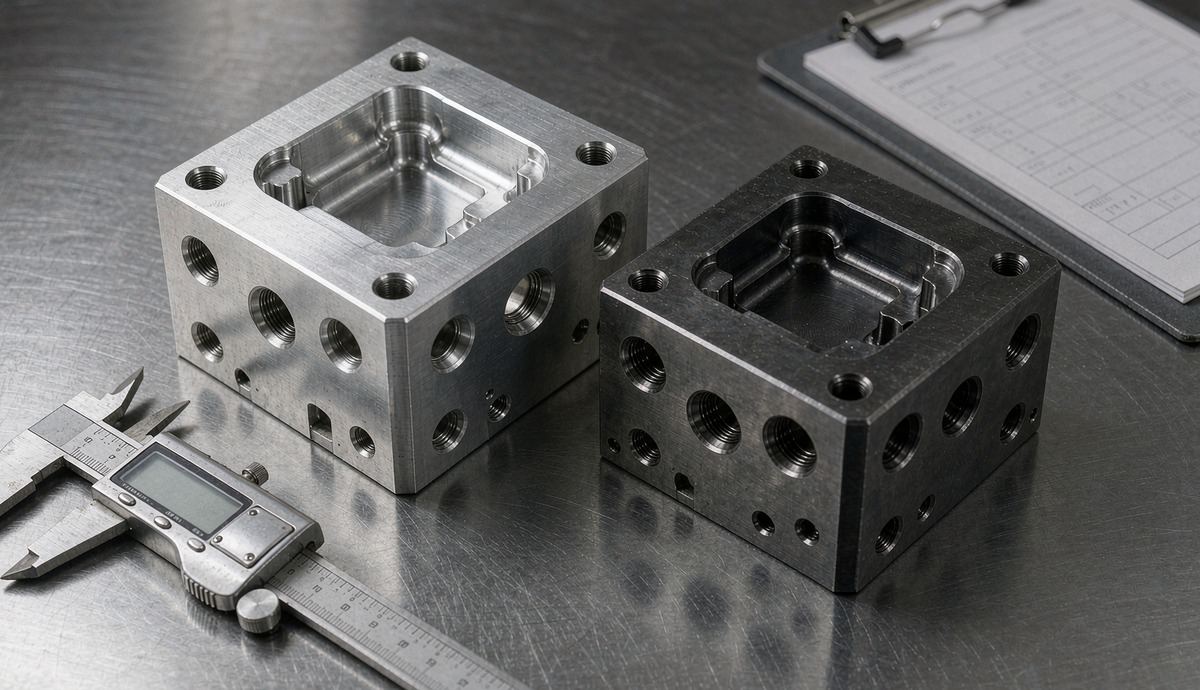
Critical dimensions should be linked to steel-safe planning where possible. A steel-safe feature is initially machined so material can be removed from the tool during tuning; adding steel back is slower and more expensive. The DFM report should identify tuning dimensions, expected shrink assumptions, and the sample stage at which final correction decisions will be made.
Worked DFM Example: A 2.0 mm ABS Electronics Housing
Consider a small ABS enclosure with a 2.0 mm nominal wall, a smooth exterior, internal stiffening ribs, and four screw bosses. The preliminary wall is within a common ABS starting range, but the selected ABS grade, longest flow path, gate, flame rating, and cosmetic specification must still be confirmed.
The first rib layout can use a 1.0鈥?.2 mm base, a maximum height near 6.0 mm, a 0.5鈥?.0 mm root radius, and 0.5鈥?掳 draft per side. If the outside is high gloss, the rib base should move toward the low end and the opposite face should be included in the appearance review. Two intersecting ribs should be relieved or staggered to prevent a locally heavy node.
The bosses can begin with a 1.0鈥?.2 mm wall and an outside diameter based on the actual screw rather than the clearance-hole diameter. Each boss should be cored, supported by thin gussets, and separated from the exterior wall. The hole diameter and engagement length must follow screw testing in the production resin because assembly torque and crack resistance cannot be approved from CAD ratios alone.
The smooth outside walls can start at 1鈥?掳 draft, while the internal walls should account for shrinkage gripping the core. A side snap should be changed to a pass-through window if packaging permits; otherwise its slide or lifter needs to be included in the tool quote. The final review should then overlay gate position, predicted weld lines, ejector pads, parting-line witness, and the critical assembly dimensions.
What Should an Injection Molding DFM Report Contain?
A useful DFM report must be traceable to the released CAD revision. Each issue should show the location, current value, proposed value, reason, and effect on function, cosmetics, tooling, or process. A screenshot without a decision owner or revised dimension is a conversation starter, not an approval record.
- Part number, CAD revision, drawing revision, unit system, and resin grade.
- Nominal wall map, thin/thick regions, transitions, and local intersections.
- Draft analysis for every mold action and the specified surface texture.
- Rib and boss measurements, sink-risk faces, fastener data, and insert process.
- Undercut list with straight-pull alternatives and chosen tooling mechanisms.
- Proposed parting line, shutoffs, slides, lifters, inserts, and ejection method.
- Gate location/type, expected weld lines, vents, and cosmetic vestiges.
- Critical-to-function dimensions, datums, measurement method, and steel-safe plan.
- Open decisions, responsible party, approval date, and change history.
The DFM report should connect directly to the supplier RFQ. The site’s engineer’s sourcing checklist for custom injection molding explains the additional mold specification, sampling, process-control, ownership, and change-control information required after part geometry is reviewed.
Pre-Tooling DFM Checklist
- Freeze the design inputs: confirm resin grade, color, additives, surface finish, annual volume, loads, regulatory needs, and show surfaces.
- Set the mold direction: define core/cavity orientation, parting line, and every secondary action before judging draft or undercuts.
- Map nominal wall: identify thin flow restrictions, thick masses, abrupt transitions, corners, and feature intersections.
- Review release: check external walls, internal cores, ribs, bosses, shutoffs, and textured faces in their own pull directions.
- Size structural features: calculate rib and boss ratios from T, then check fill, sink, steel thickness, cooling, and ejection.
- Resolve undercuts: compare a straight-pull redesign against slide, lifter, collapsible core, unscrewing core, or manual insert.
- Overlay the process concept: review gates, weld lines, vents, parting witnesses, retention, ejector marks, and automation access.
- Rationalize tolerances: keep tight controls only where function needs them and define measurement conditions.
- Approve the evidence: sign the DFM record, updated CAD, drawing, tool layout, and sample acceptance plan before cutting steel.
When a molded sample shows several defects at once, geometry and process must be separated methodically. The site’s injection molding troubleshooting guide provides a useful next step for linking visible symptoms to material, mold, machine, and process causes.
Frequently Asked Questions
Is 0.6 times nominal wall thickness always safe for a rib?
No. A 0.6T rib is a common upper starting point, not a universal approval. A high-gloss show surface, shrink-sensitive resin, heavy rib intersection, or inadequate packing path may require a thinner rib. The opposite surface and local combined thickness should be reviewed, then validated at the sampling stage.
Can zero draft be molded?
Zero draft may be technically possible on a short, polished, carefully controlled feature, but it increases drag, scuffing, ejection force, and tool wear. Zero draft should therefore be a documented exception tied to function, not a default CAD condition.
Do all undercuts require a slide?
No. Some undercuts can be eliminated with a window, moved to the parting line, formed by a shutoff, released with a lifter, or flexed as a validated bump-off. The lowest-risk choice depends on geometry, resin strain capability, finish, volume, and tool maintenance expectations.
Should mold-flow simulation replace DFM rules?
No. Simulation can estimate filling, packing, cooling, weld lines, pressure, and warpage, but the result depends on accurate material data, mesh, boundary conditions, and tool assumptions. Simulation complements geometric DFM and physical sampling; it does not replace either.
Plan Your DFM Review Before Tooling
A successful injection molded product is not created by applying isolated ratios. It comes from aligning part function, resin behavior, tool construction, molding process, cosmetics, inspection, and commercial volume before irreversible tooling decisions are made.
DJMolding supports B2B customers with plastic part DFM, mold design and manufacturing, injection molding, sampling, and production support. To review a new project, prepare the 3D CAD file, 2D drawing, resin requirement, expected annual volume, surface finish, critical dimensions, and target schedule. Contact DJMolding for a project review, or explore the website for more information about custom injection molding and tooling capabilities.
