


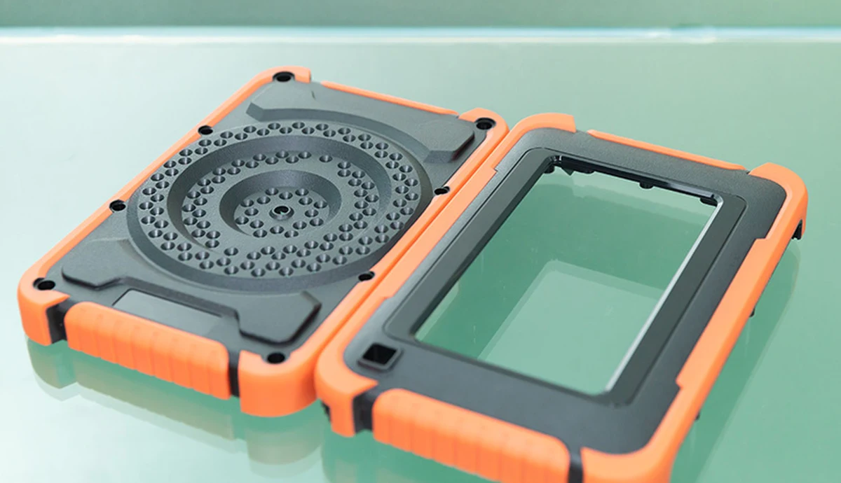
Designing Complex Multi-Material Components Using Two-Shot Injection Molding
Quick answer: Designing a multi-material part for two-shot injection molding starts with a compatible material pair, then follows a few core rules. Mold the more rigid, higher-temperature material first. Give the first shot enough thickness to resist the second injection. Design clear shut-off edges where the second material stops. Add mechanical interlocks wherever chemical bonding is uncertain. Plan gates, venting and the tool transfer method together with the part geometry. When these decisions are made before tooling, two-shot molding produces bonded, sealed and finished parts in one cycle without assembly.
This guide is written for product designers, mechanical engineers and sourcing teams developing parts that combine two materials or two colors, such as soft-touch handles, sealed housings, buttons, bumpers and lenses. It explains how to choose material pairs, set wall thicknesses, design bond and shut-off areas, select the tooling method, validate the bond and avoid the defects that most often delay two-shot projects. For the difference between two-shot molding and overmolding, see our comparison of two-shot injection molding vs overmolding.
What do existing two-shot molding design guides cover, and what do they miss?
The design guides that rank for two-shot injection molding agree on several rules: material compatibility drives bond strength, mechanical features such as undercuts, slots and through-holes help when chemical bonding is weak, the second shot should be equal to or thinner than the first shot, sudden wall changes should be avoided and shut-off areas are where flash and peeling most often appear. Several guides also recommend hot runners and careful gate placement for both shots.
These guides rarely bring the decisions together into a design sequence. They seldom compare material pairs in one table, explain how to choose between rotary, index plate, core-back and transfer tooling, show how tolerances combine across two shots, describe how to test the bond or estimate when two-shot molding becomes cheaper than overmolding or assembly. This guide covers those points so that design and tooling decisions can be made in the right order.
What is two-shot injection molding and when is it the right choice?
Two-shot injection molding is a process in which two different materials or colors are injected into the same tool in one machine cycle, forming a single part with two integrated materials. The first material forms the substrate, the tool moves the substrate to a second cavity, and the second material is injected onto or around it while the substrate is still warm, which improves bonding.
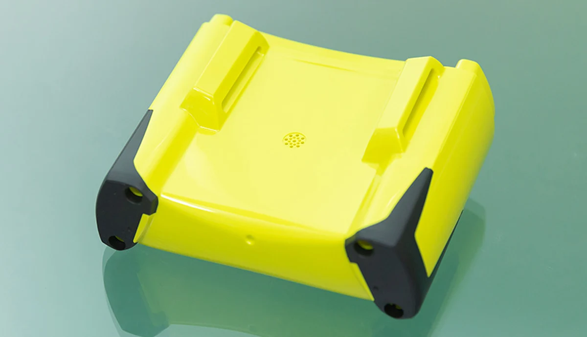
Two-shot molding is the right choice when a part needs two materials permanently joined, when volumes are high enough to justify a more complex tool and when removing assembly steps reduces cost or improves quality. It is less suitable for low volumes, very large parts or material pairs that cannot be bonded chemically or mechanically.
| Process | How the second material is added | Best for |
|---|---|---|
| Two-shot molding | In the same tool and machine cycle | Medium to high volumes, precise registration |
| Overmolding | In a second tool after the substrate is molded and transferred | Lower volumes, simpler tooling |
| Insert molding | Plastic molded around a metal or pre-made insert | Threads, contacts, metal reinforcements |
| Assembly or bonding | Separate parts joined by fasteners or adhesive | Prototypes and very low volumes |
Our service pages on two-color injection molding, overmolding and insert injection molding describe each process in more detail.
How do you choose a compatible material pair?
A compatible material pair is one in which the second material bonds chemically to the first, has a processing temperature that does not deform the substrate and shrinks in a way that does not cause warpage or delamination. Material suppliers publish adhesion grades for specific substrates, and the safest designs use a thermoplastic elastomer grade that is formulated to bond to the chosen rigid material.
| First shot (substrate) | Second shot | Typical bond | Design note |
|---|---|---|---|
| PC | TPU or PC-bonding TPE | Good chemical bond | Common for handheld devices and lenses |
| ABS or PC/ABS | TPE grade for ABS, TPU | Good chemical bond | Common for housings and grips |
| PP | SEBS-based TPE or TPV | Good chemical bond | Common for consumer and household products |
| PA (nylon) | Modified TPE grade for PA | Moderate, grade dependent | Drying and grade choice are critical |
| POM or PE | Most TPEs | Poor chemical bond | Use mechanical interlocks |
| Rigid plastic | Second rigid plastic or color | Varies with pair | Used for two-color buttons, lenses and logos |
The first shot is normally the material with the higher processing temperature and the greater rigidity, because the second shot must not melt or distort it. Hardness of the soft material, often expressed in Shore A, should be chosen for the required feel and sealing, while keeping in mind that very soft grades are harder to fill in thin sections. For a wider view of resin selection, see our guide on how to choose plastic materials for injection molding.
What wall thickness rules apply to two-shot parts?
The substrate in a two-shot part must be thick and well supported enough to resist the pressure of the second injection, and the second shot should usually be equal to or thinner than the first shot, with gradual transitions instead of sudden steps. Thin, unsupported substrate sections can flex or crush when the tool closes or when the second material is injected, which causes flash and dimensional errors.
| Feature | Design guidance | Why it matters |
|---|---|---|
| Substrate wall | Thick enough to resist second-shot pressure, often around 1.5 mm or more | Prevents deflection and crushing |
| Soft-material layer | Uniform, typically about 0.8 to 3 mm depending on grade and flow length | Ensures fill and consistent feel |
| Thickness transitions | Gradual changes, no abrupt steps | Reduces sink, voids and uneven shrink |
| Support under soft areas | Ribs or solid backing under thin substrate | Keeps the substrate stable during the second shot |
| Draft | Adequate draft on both materials, more for textured soft surfaces | Allows clean ejection without tearing |
These values are starting points that must be confirmed with flow analysis and the material supplier data. General wall thickness, draft and rib rules are covered in our injection molding design guide for wall thickness, draft, ribs and bosses.
How should the bond area and mechanical interlocks be designed?
The bond area should give the second material enough contact surface with the substrate, and mechanical interlocks should be added wherever chemical adhesion is weak, uncertain or exposed to peeling forces. Interlocks are features in the substrate, such as through-holes, undercuts, grooves or T-slots, that the second material flows into and locks behind after cooling.
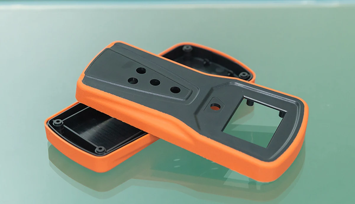
- Increase the overlap area between the two materials where loads are highest.
- Wrap the soft material around edges instead of ending it on a flat face, so it is not peeled from its edge.
- Add through-holes or undercuts that let the soft material anchor from both sides.
- Avoid ending the second material in thin feathered edges that lift easily.
- Keep bonding surfaces free of release agents and moisture.
Mechanical interlocks are especially important with material pairs that bond poorly, such as TPE on polyolefins or acetal, and in parts exposed to oils, sweat, cleaning chemicals or repeated flexing. A design that combines chemical bonding and mechanical locking is more robust than one that relies on either alone.
How should shut-off edges be designed?
Shut-off edges are the boundaries where the second-shot cavity seals against the first-shot substrate, and they are the most common source of two-shot defects. A well-designed shut-off uses a defined step or groove in the substrate, a small controlled interference between the tool and the substrate and a sealing surface wide enough to resist the injection pressure of the second material.
| Shut-off design choice | Effect |
|---|---|
| Step or groove at the material boundary | Gives a clean visual line and a positive seal |
| Small controlled interference | Prevents flash without crushing the substrate |
| Sufficient sealing width | Holds the second-shot pressure along the edge |
| Shut-off on a stable, supported area | Avoids deflection and uneven sealing |
| Avoid shut-offs on curved, thin or textured edges | Reduces flash and fraying |
Too little interference allows the soft material to flash over the substrate. Too much interference crushes or marks the substrate when the tool closes. The correct value depends on the substrate material and tool steel, and it should be agreed with the tooling team during design review.
Which tooling method should be used for a two-shot part?
The tooling method depends on part geometry, volume and how the substrate must be moved between shots. The four common methods are rotary platen or rotary table tools, index plate tools, core-back or core-pull tools and robot transfer between two cavities. Each method affects tool cost, cycle time and which designs are possible.
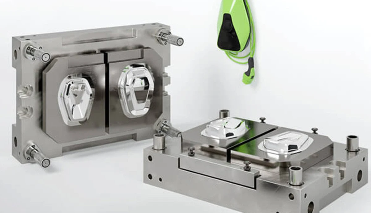
| Tooling method | How it works | Strengths | Limitations |
|---|---|---|---|
| Rotary platen or table | Moving half rotates the substrate to the second cavity | High volume, short cycles, precise registration | Needs a two-shot machine with rotation |
| Index plate | A plate lifts and rotates the substrate between stations | Handles parts that must stay on a plate | More complex tool |
| Core-back or core-pull | A core retracts to open space for the second material | No transfer, compact tool | Limited to geometries that suit core movement |
| Robot transfer | A robot moves the substrate to a second cavity | Flexible, can use standard tools | Longer cycle and handling risk |
Two-shot tools are more complex than single-material tools, which affects price and lead time. Our article on what drives injection mold cost explains the main tooling cost factors, and our injection mould design service supports these decisions.
Where should gates and vents be placed for each shot?
Gates for each shot should be placed so that each material fills its cavity evenly, with the second-shot gate directing flow along the substrate instead of against thin or unsupported walls. Vents must be placed at the end of fill for both shots, especially for the second material, because trapped air between the substrate and the soft material causes burns, short shots and weak bonding.
- Gate the second shot into thicker soft-material sections and flow toward thinner areas.
- Avoid gating the second shot directly against a thin substrate wall.
- Vent at the end of flow of the second shot along the shut-off line.
- Consider hot runners to reduce waste and control filling of both materials.
- Check gate vestiges for cosmetic and touch surfaces.
How do tolerances work across two shots?
Tolerances in a two-shot part combine the variation of the first shot, the positioning of the substrate in the second cavity and the shrinkage of the second material. Because the substrate is molded and repositioned within one tool, registration is usually more consistent than in overmolding with separate tools, but the tolerance stack still needs to be planned.
| Source of variation | How to control it |
|---|---|
| First-shot dimensions | Stable process and gauge-checked substrate features |
| Substrate location in the second cavity | Robust locating features and supported shut-offs |
| Different shrinkage of two materials | Material data, flow simulation and compensation in the tool |
| Soft-material compression | Define measurement methods for soft features |
For tight-tolerance electronic parts, our article on achieving sub-millimeter tolerances in precision electronic molding explains how tooling and process control hold critical dimensions.
How should the bond and the finished part be validated?
The bond and the finished part should be validated with tests that represent real use, not only visual inspection. A two-shot part that looks perfect can still delaminate after thermal cycling, chemical exposure or repeated flexing, so the validation plan should be agreed during design and repeated at first article and in production.
| Test | What it checks |
|---|---|
| Peel test | Force needed to separate the soft material from the substrate |
| Pull-off or torque test | Retention of knobs, buttons and grips |
| Thermal cycling | Bond stability through hot and cold cycles |
| Chemical exposure | Resistance to oils, sweat, cleaners and sunscreen |
| Flex and drop tests | Durability of seals, bumpers and edges |
| Dimensional inspection | Critical features of both shots against the drawing |
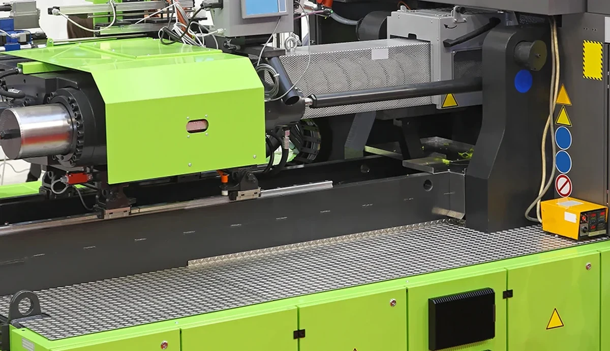
Prototype samples are the best time to discover bond and fit issues. Our article on moving from CAD to functional part with a prototype molding supplier explains how early samples reduce risk before production tooling.
What are the most common two-shot molding defects and their causes?
The most common two-shot molding defects are delamination, flash at the shut-off, substrate deformation, trapped gas, short shots in thin soft sections and warpage. Most of them can be traced to design decisions about material pairing, wall thickness, shut-off design or venting, which is why design review prevents more defects than process adjustment.
| Defect | Likely cause | Design or process remedy |
|---|---|---|
| Delamination | Incompatible materials, cold or contaminated substrate | Bonding grade, interlocks, controlled substrate temperature |
| Flash at shut-off | Too little interference or deflecting substrate | Supported shut-off with defined interference |
| Crushed or marked substrate | Too much interference | Adjust shut-off and tool fit |
| Burns or short shots | Trapped air in the second shot | Vents at end of fill |
| Warpage | Different shrinkage between materials | Balanced geometry and material selection |
| Color bleed or blending | Second shot melting the substrate surface | Adjust temperatures and material order |
Our page on solutions to common injection molding defects covers general defect causes that also apply to each shot.
When does two-shot molding cost less than overmolding or assembly?
Two-shot molding usually costs less than overmolding or assembly at medium to high volumes, because the higher tooling investment is spread over many parts while the process removes transfer, assembly and adhesive steps. At low volumes, overmolding with simpler tools or assembling separate parts is often more economical, because the tooling saving outweighs the higher labor cost per part.
| Cost factor | Two-shot molding | Overmolding | Assembly of separate parts |
|---|---|---|---|
| Tooling investment | Highest | Medium, two simpler tools | Lower, two standard tools |
| Labor per part | Lowest | Medium, transfer between tools | Highest, assembly step |
| Cycle efficiency | High | Medium | Lower overall |
| Bond and seal quality | High and consistent | Good | Depends on fasteners or adhesive |
| Best volume range | Medium to high | Low to medium | Prototypes and very low |
The break-even point depends on part size, cavitation, labor cost and quality requirements, so it should be calculated for each project. Our injection molding cost estimator guide shows how to compare options early.
What should a two-shot design review checklist include?
A two-shot design review should confirm every decision that affects bonding, filling, sealing and tooling before steel is cut. Reviewing the checklist with the molder at the design stage avoids most expensive tool changes later.
- Material pair confirmed with adhesion data, including grade and hardness.
- Shot order defined, with the rigid, higher-temperature material first.
- Substrate thickness and support under soft areas checked.
- Bond area and mechanical interlocks defined.
- Shut-off edges located on supported surfaces with agreed interference.
- Gates and vents planned for both shots.
- Tooling method selected and confirmed with the machine available.
- Tolerance stack and measurement methods agreed.
- Validation tests and acceptance criteria defined.
Frequently asked questions
Which material should be molded first in two-shot molding?
The material with the higher processing temperature and greater rigidity is normally molded first. This allows the second, often softer material to be injected without melting or deforming the substrate.
Can any two plastics be combined in two-shot molding?
No. Some material pairs bond well chemically, while others, such as many elastomers on acetal or polyethylene, bond poorly. Poorly bonding pairs need mechanical interlocks, and some combinations are not practical at all because of temperature or shrinkage differences.
Is two-shot molding the same as two-color molding?
Two-color molding is a type of two-shot molding that uses two colors of the same or similar material. Two-shot molding also includes combinations of different materials, such as a rigid substrate with a soft elastomer.
How thick should the soft layer be in a two-shot part?
The soft layer is commonly designed around 0.8 to 3 mm, depending on the material grade, flow length and required feel. Thinner sections are harder to fill, so the final value should be confirmed with flow analysis and material data.
Can liquid silicone rubber be used in two-shot molding?
Yes. Self-adhesive liquid silicone rubber grades can be molded onto compatible thermoplastic substrates in multi-shot processes, but they require heated cavities for curing and careful thermal separation in the tool. Our LSR injection molding page describes this process.
How long does it take to build a two-shot mold?
A two-shot mold usually takes longer to design and build than a single-material mold, because it includes two cavities, transfer mechanisms and more complex shut-offs. The exact lead time depends on part size, cavitation and design complexity.
Develop your two-shot parts with DJmolding
Huizhou DJmolding Co., Ltd. has been a plastic injection molding and mould manufacturer in Guangdong, China, since 2010. The company designs and builds injection molds and produces plastic parts for household appliances, medical equipment, electronic equipment, automotive components and safety and monitoring products, supporting both low volume and high volume manufacturing.
For product developers, OEMs and sourcing teams, DJmolding offers:
- Two-color and two-shot injection molding, overmolding and insert molding for multi-material parts.
- In-house mould design and mould manufacturing with CNC machining, precision milling, EDM, wire cutting and grinding equipment.
- High-precision molding with part tolerances that can reach plus or minus 0.01 mm for suitable designs.
- Liquid silicone rubber molding, with silicone products approved by FDA, SGS and LFGB, and a factory that has passed BSCI audit.
- Rapid prototyping, low volume and high volume production with a defined quality control system.
To review your multi-material design, upload your 3D CAD files and tell us the materials, colors, expected volume and critical requirements. Contact the engineering team at info@djmolding.com, call +86-752-6682869 or +86-13352636504, or use the contact page. You can also learn more about DJmolding.
