


Achieving Sub-Millimeter Tolerances in Precision Electronic Plastic Molding
Quick answer: Precision injection molding can hold sub-millimeter tolerances on electronic plastic parts:
- Small critical features: typically ±0.02 to ±0.05 mm.
- Larger dimensions: typically ±0.05 to ±0.10 mm.
Reaching those numbers takes five things working together:
- a dimensionally stable material, such as LCP, PPS, PBT or PC
- a part design with uniform walls and clear datums
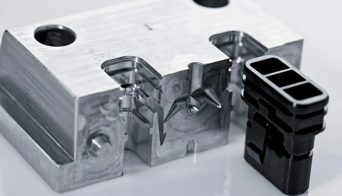
- a hardened steel mold machined to a few microns and tuned steel-safe
- a scientifically developed and monitored molding process
- a measurement system that is at least ten times more precise than the tolerance
Tight tolerances should be applied only to features that control fit or function, because every reduction in tolerance raises tooling, inspection and part cost.
What this guide adds: it goes beyond general advice. It covers:
- tolerance tiers by part size
- worked shrinkage calculations
- material data for electronics resins
- the effect of cavity count
- post-mold dimensional change
- measurement capability rules
- Cpk targets
- a tolerance stack-up example for an electronic assembly
- an RFQ checklist for buyers
For general part design rules, see the injection molding DFM design guide.
What does a sub-millimeter tolerance mean in electronic plastic molding?
A sub-millimeter tolerance is a permitted dimensional variation smaller than 1 mm. In electronic molding, it usually means variation measured in hundredths of a millimeter. Connector housings, sensor carriers, camera module holders, battery frames and device enclosures contain features that must locate metal terminals, printed circuit boards, lenses or seals to within a few hundredths of a millimeter. If a terminal cavity is 0.05 mm out of position, a fine-pitch connector may not mate. If a housing wall is 0.1 mm too thick, a device may not close or a seal may leak.
Tolerances in molding are usually grouped into practical tiers. The achievable tier depends mainly on the size of the dimension, the material and whether the dimension is formed by one mold half or crosses the parting line.
| Tolerance tier | Typical range for dimensions up to about 25 mm | Typical use in electronics |
|---|---|---|
| Commercial | ±0.10 to ±0.20 mm | Non-critical covers, brackets and cosmetic parts |
| Fine | ±0.05 to ±0.10 mm | Enclosure fits, snap fits, PCB locating features |
| Precision | ±0.02 to ±0.05 mm | Connector housings, terminal cavities, sensor carriers |
| High precision | ±0.01 to ±0.02 mm | Fine-pitch connector pitch, optical alignment features, small critical features |
Which electronic parts need sub-millimeter tolerances?
Electronic parts need sub-millimeter tolerances wherever plastic positions a metal, optical or electronic component. Common examples include:
- board-to-board and wire-to-board connector housings with terminal pitches of 0.5 to 2.54 mm
- USB and memory card connector shells and inserts
- LED light guides and lens holders
- camera module brackets
- sensor and switch housings
- battery holders and cell frames
- PCB support frames
- SIM trays
- enclosures with tight gasket or ultrasonic welding interfaces
Not every dimension on these parts needs the tightest tier. A typical connector housing may have a handful of critical-to-function dimensions, such as terminal pitch, cavity width, latch position and mating face flatness, while its outer profile can use a fine or commercial tolerance. Identifying those critical dimensions early is the first step toward holding them.
How do tolerance standards define what is achievable?
Tolerance standards for molded plastic parts link the achievable tolerance to the size of the dimension and to the process capability of the material. The international standard ISO 20457 defines tolerance groups for molded plastic parts and replaced the earlier German standard DIN 16742. In both systems, tolerance widens as the nominal dimension grows. A 5 mm feature can be held much tighter than a 150 mm feature in the same material, because shrinkage variation scales with length.
These standards also separate mold-bound and non-mold-bound dimensions:
- Mold-bound dimensions: formed entirely within one mold half, such as the distance between two holes in the same cavity insert. They can be held tighter.
- Non-mold-bound dimensions: cross the parting line or depend on a slide or lifter, such as wall thickness between core and cavity. They vary more, because they include mold closing and alignment variation.
Designers can hold critical features tighter by placing them within a single mold half.
How does shrinkage limit dimensional accuracy?
Shrinkage is the main reason molded dimensions vary. Plastics shrink as they cool from melt to room temperature, and the amount depends on material, filler, wall thickness, pressure, temperature and flow direction. The mold is cut larger than the part by the expected shrinkage, so what matters for tolerance is how much shrinkage varies, not its average value.
Worked example: A 50 mm dimension molded in a material with a nominal shrinkage of 0.5 percent requires a mold dimension of about 50.25 mm. If actual shrinkage varies by ±0.1 percent between shots, cavities or flow directions, the part varies by ±0.05 mm. On a 10 mm feature, the same variation produces only ±0.01 mm. This is why small features can be held to precision tolerances while long dimensions need wider ones.
Glass-filled and liquid crystal polymer materials add anisotropy:
- Glass-filled grades: shrink less in the flow direction, where fibers align, than across the flow.
- Liquid crystal polymers: molecular orientation produces the same effect.
For a 30 percent glass-filled PBT, flow shrinkage may be about 0.3 percent and cross-flow shrinkage about 0.8 to 1.0 percent. That difference causes warpage unless gate location and wall design control the flow pattern. Gate design is discussed in types of gating systems for plastic injection mold design.
Which materials are best for tight-tolerance electronic parts?
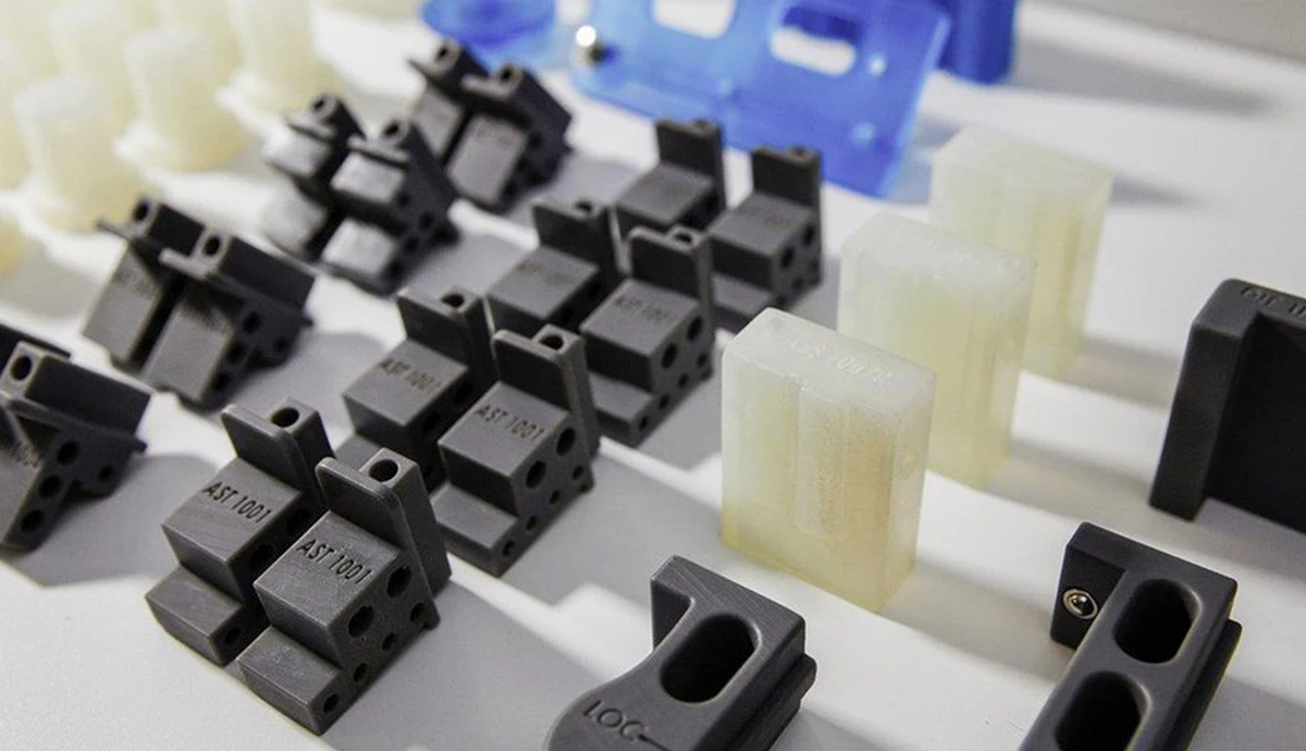
The best materials for tight-tolerance electronic parts combine low and predictable shrinkage, low moisture absorption and enough heat resistance for the assembly process. Parts that pass through lead-free reflow soldering at peak temperatures around 260 °C need high-temperature resins such as LCP, PPS or high-temperature polyamides. Parts assembled after soldering can use PBT, PC or PC/ABS.
| Material | Typical shrinkage | Moisture effect | Typical electronic uses |
|---|---|---|---|
| LCP, glass filled | About 0.1 to 0.6 percent, strongly anisotropic | Very low | Fine-pitch and SMT connectors, sockets, coil bobbins |
| PPS, 40 percent glass | About 0.2 to 0.5 percent | Very low | Sensor housings, connectors, high-temperature parts |
| PBT, 30 percent glass | About 0.3 to 1.0 percent | Low | Connectors, relay and switch housings |
| PA66, 30 percent glass | About 0.3 to 1.0 percent | Significant swelling as it absorbs moisture | Connectors, terminal blocks, brackets |
| PC | About 0.5 to 0.7 percent | Low | Enclosures, light guides, lens holders |
| PC/ABS | About 0.5 to 0.7 percent | Low | Device enclosures and covers |
| POM | About 1.8 to 2.2 percent | Low | Small gears and mechanisms, less suitable for tight fits |
Values vary by grade and processing and should be confirmed with the resin data sheet. Polyamides deserve special attention: an unfilled PA66 part can grow several tenths of a percent as it absorbs moisture from the air, so dimensions measured dry after molding may change in service. Material properties are explained in the PBT injection molding guide and the nylon injection molding guide.
How should part design support sub-millimeter tolerances?
Part design determines most of the tolerance that can be achieved. Key rules for electronic parts include:
- Uniform walls: keep wall thickness uniform, typically 0.6 to 2.0 mm for electronic housings, so cooling and shrinkage are even.
- Coring: core out thick sections that would sink or shrink unpredictably.
- Feature placement: place critical features within one mold half and away from slides and lifters.
- Symmetry: design symmetrical ribs and walls to limit warpage.
- Datums: define datums that match how the part locates in the assembly.
Geometric dimensioning and tolerancing (GD&T) is especially useful for electronics. Position, profile and flatness tolerances tied to functional datums describe what the assembly actually needs. They often allow wider individual tolerances than plus and minus dimensions from an arbitrary edge. For example, a position tolerance on terminal cavities relative to the mating face datum controls connector mating directly.
Designers should also mark critical-to-function dimensions on the drawing and leave non-critical dimensions at general tolerances. A drawing that applies ±0.02 mm to every dimension usually cannot be met economically. A drawing that applies it to the six dimensions that matter usually can. Insert molded parts, where metal terminals are molded into plastic, add terminal position tolerances. They are covered on the insert injection molding page.
How do mold design and mold making achieve micron-level accuracy?
The mold sets the upper limit on part accuracy. A precision electronic mold needs:
- Machined accuracy: cavity and core inserts cut by high-speed CNC milling, sinker EDM, wire EDM and precision grinding, typically to within about ±0.002 to ±0.005 mm on critical features.
- Steel: hardened tool steels, often around 48 to 54 HRC, keep these dimensions through hundreds of thousands or millions of cycles.
- Alignment: interlocks and taper locks align core and cavity on every shot.
- Cooling: balanced cooling channels keep cavity surface temperatures even.
- Venting: precise venting avoids short shots and burns on thin features.
Cooling design has an outsized effect on tolerance, because uneven mold temperature causes uneven shrinkage and warpage. Conformal or closely spaced cooling around thin connector cores keeps temperatures within a few degrees across the cavity. Cooling principles are explained in plastic injection mold cooling system design.
Experienced precision toolmakers also use a steel-safe approach:
- Critical dimensions are cut so that the first trial parts err on the side where metal can be removed, not added.
- After the first trial, typically called T1, parts are measured and the mold is adjusted to bring dimensions to nominal.
- Further trials confirm the correction.
This approach is more reliable than trying to predict shrinkage perfectly, because it uses measured data from the actual mold, material and process.
How does cavity count affect tolerance?
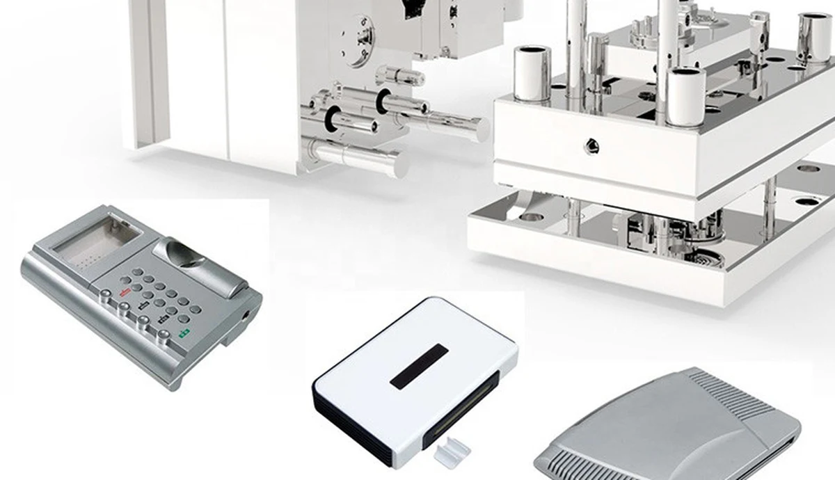
Every additional cavity adds a source of variation. Each cavity is machined separately and fills through a different runner path, so parts from cavity 1 and cavity 8 differ slightly even when every cavity is within tolerance. For the tightest tolerances, molders often use one to four cavities with careful balance. Small connectors made in high volume may use 8 to 32 cavities, but these need:
- balanced hot runners or runner systems
- cavity identification marks
- cavity-by-cavity measurement during qualification
Buyers should ask for dimensional data from every cavity, not a single sample. A common qualification rule is to measure a set of parts from each cavity and confirm that cavity-to-cavity variation uses only a small part of the tolerance. If one cavity runs off nominal, it can be corrected individually or blocked while the others continue to run.
How does process control hold tolerances in production?
Process control keeps the dimensions achieved during qualification stable over millions of parts. Scientific molding methods develop the process from data:
- a viscosity study to find a stable injection speed
- a gate freeze study to set hold time
- a cavity balance study
- a pressure drop study
- a designed experiment to find the process window in which all critical dimensions stay within tolerance
The resulting process sheet records the settings, and production monitoring keeps them within limits.
Key controls for sub-millimeter electronic parts include:
- Material drying: correct drying for hygroscopic resins such as PBT, PA and LCP.
- Mold temperature: held within about ±1 to 2 °C by temperature control units.
- Machine size: a machine where the shot uses roughly 20 to 80 percent of the barrel capacity.
- Repeatability: all-electric or servo-driven machines give high repeatability.
- Cavity pressure sensors: on critical tools, these detect changes in filling and packing before they appear as out-of-tolerance parts.
- Regrind: limits on regrind for critical parts.
The quality system that supports these controls is described on the quality control system page.
Why do dimensions change after molding?
Molded parts continue to change after ejection, so measurements taken too early can be misleading:
- Post-mold shrinkage: continues for hours to days as the part cools fully and polymer chains relax. Semi-crystalline materials such as POM, PBT and PA change more than amorphous materials such as PC.
- Moisture: polyamides grow as they absorb moisture.
- Stress relief: annealing or heating during reflow soldering can relieve molded-in stress and change flatness.
Good practice is to define the measurement condition on the drawing or in the quality plan. One example: measure after conditioning for 24 to 48 hours at 23 °C and 50 percent relative humidity. For parts that pass through reflow, measure flatness and position after a simulated reflow cycle as well as before. Coplanarity of connector terminals after reflow, often specified at around 0.1 mm or less, is a common acceptance criterion for surface mount connectors.
How should sub-millimeter tolerances be measured?
Measurement must be clearly more precise than the tolerance being checked. Two common rules of thumb:
- Resolution: the measuring instrument should resolve about one tenth of the tolerance band.
- Gauge capability: a gauge repeatability and reproducibility (GR&R) study should show measurement variation below about 10 percent of the tolerance. Up to 30 percent may be accepted for less critical features.
For a ±0.02 mm tolerance, the 0.04 mm band calls for an instrument that resolves about 0.004 mm and a well-controlled method.
| Method | Strengths | Typical use |
|---|---|---|
| Coordinate measuring machine (CMM) | High accuracy, full GD&T evaluation | First article inspection, capability studies |
| Optical or vision measuring system | Fast, non-contact, good for small flexible features | Terminal cavities, pitch, small holes, in-process checks |
| Industrial CT scanning | Measures internal features and full geometry | Complex connectors, insert molded parts, mold correction |
| Go and no-go gauges and fixtures | Fast functional check at the press | Production monitoring of critical fits |
Fixtures should hold the part on its functional datums, and measurements should be taken at a controlled temperature, since plastic expands noticeably with heat. The reference temperature for dimensional measurement is 20 °C. Inspection methods for first articles are also covered in from CAD to functional part with a prototype injection molding supplier.
What process capability should buyers expect?
Holding a tolerance once is not the goal. The goal is holding it on every part, which is measured by process capability:
- Cpk: compares the distance from the process mean to the nearest tolerance limit with three standard deviations of the process.
- Minimum target: a Cpk of 1.33 is a common minimum for critical dimensions in electronics and automotive supply chains.
- Safety-critical or high-volume features: often a Cpk of 1.67.
A practical way to read these numbers: for a ±0.03 mm tolerance and a centered process, a Cpk of 1.33 requires a process standard deviation of about 0.0075 mm, and a Cpk of 1.67 requires about 0.006 mm. If initial capability is too low, the options are:
- center the process by adjusting the mold
- reduce variation through process or cooling improvements
- review whether the tolerance can be widened without affecting function
Capability expectations for regulated supply chains are discussed in the PPAP and IATF 16949 guide.
How do tolerances stack up in an electronic assembly?
Individual part tolerances combine in an assembly, so a tolerance stack-up analysis should guide which tolerances are tight.
Worked example: A connector housing locates on a PCB, and the PCB sits in a molded enclosure, so the connector must align with an opening in the enclosure wall. Assume four contributors:
- connector position on the PCB, ±0.05 mm
- PCB locating hole to enclosure boss, ±0.05 mm
- enclosure boss to opening, ±0.08 mm
- connector housing outer profile, ±0.03 mm
Two ways to combine them:
- Worst case: the total is ±0.21 mm.
- Root sum square (RSS): this statistical method assumes independent, centered processes, and the total is about ±0.11 mm.
If the opening must clear the connector by at least 0.15 mm per side, the stack shows two things. The design works statistically but not in the worst case, and the enclosure boss-to-opening tolerance is the largest contributor. Tightening that one molded dimension, or adding a locating feature closer to the connector, is more effective than tightening every part. Stack-up analysis therefore saves cost by showing where precision is needed.
How do tighter tolerances affect cost?
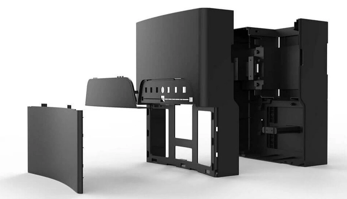
Tighter tolerances raise cost in tooling, molding and inspection. The table below compares typical effects as tolerances move from commercial to high precision.
| Cost driver | Commercial tolerance | Precision and high precision tolerance |
|---|---|---|
| Mold steel and machining | Standard steels and machining | Hardened steels, grinding, wire EDM, more inserts |
| Mold trials and tuning | One or two trials | Several steel-safe correction loops |
| Cavity count | Higher cavitation possible | Fewer cavities or more balancing effort |
| Process control | Standard monitoring | Scientific molding, cavity pressure monitoring |
| Inspection | Sampling with simple gauges | CMM, vision or CT, capability studies |
| Scrap risk | Low | Higher until the process is capable |
The most economical approach is to apply tight tolerances only to critical features, confirm them through stack-up analysis, and agree tolerances with the molder during DFM review before the mold is cut. Cost factors are detailed in the injection molding cost guide.
What should an RFQ for tight-tolerance electronic parts include?
A complete RFQ helps the molder quote accurately and plan the right mold and inspection approach. It should include:
- 3D CAD models and 2D drawings with GD&T, datums and critical-to-function dimensions clearly marked
- material grade, color and any flame rating such as UL 94 V-0
- assembly process, including reflow soldering temperature if relevant
- annual volume and expected mold life
- preferred cavity count, if any
- measurement conditions and required inspection methods
- capability targets, such as Cpk 1.33 or 1.67 on critical dimensions
- documentation requirements such as first article inspection reports, capability studies and material certificates
- details of mating parts or assemblies that the molded part must fit
Molders should respond with a DFM report that reviews wall thickness, gate location, parting line, critical dimension placement, expected shrinkage and warpage, and any tolerance that cannot be met economically, with suggested alternatives.
Frequently asked questions
What is the tightest tolerance achievable in plastic injection molding?
For small mold-bound features in stable materials such as LCP or PPS, precision molders can hold about ±0.01 to ±0.02 mm. Larger dimensions, features crossing the parting line and less stable materials need wider tolerances, typically ±0.05 mm or more.
Why does a molded part measure differently a day after molding?
Molded parts continue to shrink as they cool and relax, and some materials such as polyamides absorb moisture and grow. Measuring after a defined conditioning period gives consistent, comparable results.
Is LCP always the best material for precision connectors?
LCP flows into very thin walls, has very low shrinkage and survives reflow soldering, which makes it a leading choice for fine-pitch connectors. Its strong anisotropy and weak weld lines need careful gate and design planning. PPS, PBT or high-temperature polyamides may suit less demanding parts at lower cost.
Does more cavities mean less precision?
More cavities add cavity-to-cavity variation, but well-balanced multi-cavity molds can still hold precision tolerances. The key is runner balance, cooling balance and measurement of every cavity during qualification.
Develop your precision electronic molded parts with DJmolding
DJmolding is a plastic injection molding and mould manufacturer that supports electronics brands, OEMs and contract manufacturers. Its services cover:
- DFM review and injection mould design
- precision injection mould manufacturing
- insert molding and overmolding for terminal and connector parts
- rapid prototyping
- low and high volume production of custom plastic injection molded parts
The team works from your CAD files and critical-to-function requirements to recommend materials, gate locations, cavity count and inspection methods that hold your tolerances economically.
If you are developing connector housings, sensor carriers, device enclosures or other tight-tolerance electronic parts, send your drawings, material requirements, annual volumes and target tolerances. DJmolding will return a DFM review and quotation. Contact DJmolding to start your precision electronic molding project.
